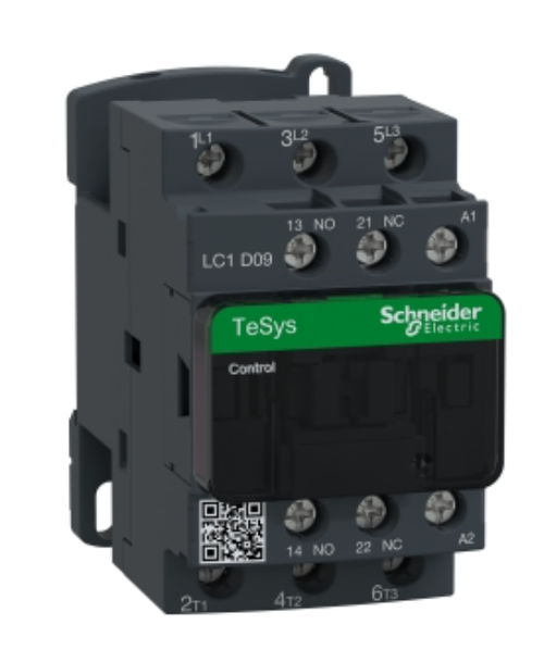
3-Pole Contactors-AC Control Screw Clamp Terminals
SKU: bc-722
$24.75
Currently out of stock — contact us for lead times
Description
Main - LC1D09UL range TeSysTeSys Deca product name TeSys DTeSys Deca product or component type Contactor device short name LC1D contactor application Motor controlResistive load utilisation category AC-3AC-4AC-1AC-3e poles description 3P power pole contact composition 3 NO [Ue] rated operational voltage Power circuit: <= 690 V AC 25...400 HzPower circuit: <= 300 V DC [Ie] rated operational current 9 A (at <60 °C) at <= 440 V AC AC-3 for power circuit25 A (at <60 °C) at <= 440 V AC AC-1 for power circuit9 A (at <60 °C) at <= 440 V AC AC-3e for power circuit motor power kW 2.2 kW at 220...230 V AC 50/60 Hz (AC-3)4 kW at 380...400 V AC 50/60 Hz (AC-3)4 kW at 415...440 V AC 50/60 Hz (AC-3)5.5 kW at 500 V AC 50/60 Hz (AC-3)5.5 kW at 660...690 V AC 50/60 Hz (AC-3)2.2 kW at 400 V AC 50/60 Hz (AC-4)2.2 kW at 220...230 V AC 50/60 Hz (AC-3e)4 kW at 380...400 V AC 50/60 Hz (AC-3e)4 kW at 415...440 V AC 50/60 Hz (AC-3e)5.5 kW at 500 V AC 50/60 Hz (AC-3e)5.5 kW at 660...690 V AC 50/60 Hz (AC-3e) motor power HP (UL / CSA) 1 hp at 230/240 V AC 50/60 Hz for 1 phase motors2 hp at 200/208 V AC 50/60 Hz for 3 phases motors2 hp at 230/240 V AC 50/60 Hz for 3 phases motors5 hp at 460/480 V AC 50/60 Hz for 3 phases motors7.5 hp at 575/600 V AC 50/60 Hz for 3 phases motors0.33 hp at 115 V AC 50/60 Hz for 1 phase motors control circuit type AC at 50/60 Hz [Uc] control circuit voltage 240 V AC 50/60 Hz auxiliary contact composition 1 NO + 1 NC [Uimp] rated impulse withstand voltage 6 kV conforming to IEC 60947 overvoltage category III [Ith] conventional free air thermal current 25 A (at 60 °C) for power circuit10 A (at 60 °C) for signalling circuit Irms rated making capacity 250 A at 440 V for power circuit conforming to IEC 60947140 A AC for signalling circuit conforming to IEC 60947-5-1250 A DC for signalling circuit conforming to IEC 60947-5-1 rated breaking capacity 250 A at 440 V for power circuit conforming to IEC 60947 [Icw] rated short-time withstand current 105 A 40 °C - 10 s for power circuit210 A 40 °C - 1 s for power circuit30 A 40 °C - 10 min for power circuit61 A 40 °C - 1 min for power circuit100 A - 1 s for signalling circuit120 A - 500 ms for signalling circuit140 A - 100 ms for signalling circuit associated fuse rating 10 A gG for signalling circuit conforming to IEC 60947-5-125 A gG at <= 690 V coordination type 1 for power circuit20 A gG at <= 690 V coordination type 2 for power circuit average impedance 2.5 mOhm - Ith 25 A 50 Hz for power circuit [Ui] rated insulation voltage Power circuit: 690 V conforming to IEC 60947-4-1Power circuit: 600 V CSA certifiedPower circuit: 600 V UL certifiedSignalling circuit: 690 V conforming to IEC 60947-1Signalling circuit: 600 V CSA certifiedSignalling circuit: 600 V UL certified electrical durability 0.6 Mcycles 25 A AC-1 at Ue <= 440 V2 Mcycles 9 A AC-3 at Ue <= 440 V2 Mcycles 9 A AC-3e at Ue <= 440 V power dissipation per pole 1.56 W AC-10.2 W AC-30.2 W AC-3e Front cover With mounting support RailPlate standards CSA C22.2 No 14EN 60947-4-1EN 60947-5-1IEC 60947-4-1IEC 60947-5-1UL 508IEC 60335-1 product certifications BVULGOSTCSARINAGLLROS (Lloyds register of shipping)CCCDNVUKCA connections - terminals Power circuit: screw clamp terminals 1 cable(s) 1…4 mm²flexible without cable endPower circuit: screw clamp terminals 2 cable(s) 1…4 mm²flexible without cable endPower circuit: screw clamp terminals 1 cable(s) 1…4 mm²flexible with cable endPower circuit: screw clamp terminals 2 cable(s) 1…2.5 mm²flexible with cable endPower circuit: screw clamp terminals 1 cable(s) 1…4 mm²solid without cable endPower circuit: screw clamp terminals 2 cable(s) 1…4 mm²solid without cable endControl circuit: screw clamp terminals 1 cable(s) 1…4 mm²flexible without cable endControl circuit: screw clamp terminals 2 cable(s) 1…4 mm²flexible without cable endControl circuit: screw clamp terminals 1 cable(s) 1…4 mm²flexible with cable endControl circuit: screw clamp terminals 2 cable(s) 1…2.5 mm²flexible with cable endControl circuit: screw clamp terminals 1 cable(s) 1…4 mm²solid without cable endControl circuit: screw clamp terminals 2 cable(s) 1…4 mm²solid without cable end tightening torque Power circuit: 1.7 N.m - on screw clamp terminals - with screwdriver flat Ø 6 mmPower circuit: 1.7 N.m - on screw clamp terminals - with screwdriver Philips No 2Control circuit: 1.7 N.m - on screw clamp terminals - with screwdriver flat Ø 6 mmControl circuit: 1.7 N.m - on screw clamp terminals - with screwdriver Philips No 2Control circuit: 1.7 N.m - on screw clamp terminals - with screwdriver pozidriv No 2Power circuit: 2.5 N.m - on screw clamp terminals - with screwdriver pozidriv No 2 operating time 12...22 ms closing4...19 ms opening safety reliability level B10d = 1369863 cycles contactor with nominal load conforming to EN/ISO 13849-1B10d = 20000000 cycles contactor with mechanical load conforming to EN/ISO 13849-1 mechanical durability 15 Mcycles maximum operating rate 3600 cyc/h 60 °C Complementary coil technology Without built-in suppressor module control circuit voltage limits 0.3...0.6 Uc (-40…70 °C):drop-out AC 50/60 Hz0.8...1.1 Uc (-40…60 °C):operational AC 50 Hz0.85...1.1 Uc (-40…60 °C):operational AC 60 Hz1...1.1 Uc (60…70 °C):operational AC 50/60 Hz inrush power in VA 70 VA 60 Hz cos phi 0.75 (at 20 °C)70 VA 50 Hz cos phi 0.75 (at 20 °C) hold-in power consumption in VA 7.5 VA 60 Hz cos phi 0.3 (at 20 °C)7 VA 50 Hz cos phi 0.3 (at 20 °C) heat dissipation 2…3 W at 50/60 Hz auxiliary contacts type Type mechanically linked 1 NO + 1 NC conforming to IEC 60947-5-1type mirror contact 1 NC conforming to IEC 60947-4-1 signalling circuit frequency 25...400 Hz minimum switching current 5 mA for signalling circuit minimum switching voltage 17 V for signalling circuit non-overlap time 1.5 ms on de-energisation between NC and NO contact1.5 ms on energisation between NC and NO contact insulation resistance > 10 MOhm for signalling circuit Main - LC1D12U7 range TeSysTeSys Deca product name TeSys DTeSys Deca product or component type Contactor device short name LC1D contactor application Motor controlResistive load utilisation category AC-3AC-4AC-1AC-3e poles description 3P power pole contact composition 3 NO [Ue] rated operational voltage Power circuit: <= 690 V AC 25...400 HzPower circuit: <= 300 V DC [Ie] rated operational current 25 A (at <60 °C) at <= 440 V AC AC-1 for power circuit12 A (at <60 °C) at <= 440 V AC AC-3 for power circuit12 A (at <60 °C) at <= 440 V AC AC-3e for power circuit motor power kW 3 kW at 220...230 V AC 50/60 Hz (AC-3)5.5 kW at 380...400 V AC 50/60 Hz (AC-3)5.5 kW at 415...440 V AC 50/60 Hz (AC-3)7.5 kW at 500 V AC 50/60 Hz (AC-3)7.5 kW at 660...690 V AC 50/60 Hz (AC-3)3.7 kW at 400 V AC 50/60 Hz (AC-4)3 kW at 220...230 V AC 50/60 Hz (AC-3e)5.5 kW at 380...400 V AC 50/60 Hz (AC-3e)5.5 kW at 415...440 V AC 50/60 Hz (AC-3e)7.5 kW at 500 V AC 50/60 Hz (AC-3e)7.5 kW at 660...690 V AC 50/60 Hz (AC-3e) motor power HP (UL / CSA) 0.5 hp at 115 V AC 50/60 Hz for 1 phase motors2 hp at 230/240 V AC 50/60 Hz for 1 phase motors3 hp at 200/208 V AC 50/60 Hz for 3 phases motors3 hp at 230/240 V AC 50/60 Hz for 3 phases motors7.5 hp at 460/480 V AC 50/60 Hz for 3 phases motors10 hp at 575/600 V AC 50/60 Hz for 3 phases motors control circuit type AC at 50/60 Hz [Uc] control circuit voltage 240 V AC 50/60 Hz auxiliary contact composition 1 NO + 1 NC [Uimp] rated impulse withstand voltage 6 kV conforming to IEC 60947 overvoltage category III [Ith] conventional free air thermal current 25 A (at 60 °C) for power circuit10 A (at 60 °C) for signalling circuit Irms rated making capacity 250 A at 440 V for power circuit conforming to IEC 60947140 A AC for signalling circuit conforming to IEC 60947-5-1250 A DC for signalling circuit conforming to IEC 60947-5-1 rated breaking capacity 250 A at 440 V for power circuit conforming to IEC 60947 [Icw] rated short-time withstand current 105 A 40 °C - 10 s for power circuit210 A 40 °C - 1 s for power circuit30 A 40 °C - 10 min for power circuit61 A 40 °C - 1 min for power circuit100 A - 1 s for signalling circuit120 A - 500 ms for signalling circuit140 A - 100 ms for signalling circuit associated fuse rating 10 A gG for signalling circuit conforming to IEC 60947-5-140 A gG at <= 690 V coordination type 1 for power circuit25 A gG at <= 690 V coordination type 2 for power circuit average impedance 2.5 mOhm - Ith 25 A 50 Hz for power circuit [Ui] rated insulation voltage Power circuit: 690 V conforming to IEC 60947-4-1Power circuit: 600 V CSA certifiedPower circuit: 600 V UL certifiedSignalling circuit: 690 V conforming to IEC 60947-1Signalling circuit: 600 V CSA certifiedSignalling circuit: 600 V UL certified electrical durability 2 Mcycles 12 A AC-3 at Ue <= 440 V0.8 Mcycles 25 A AC-1 at Ue <= 440 V2 Mcycles 12 A AC-3e at Ue <= 440 V power dissipation per pole 0.36 W AC-31.56 W AC-10.36 W AC-3e Front cover With mounting support RailPlate standards CSA C22.2 No 14EN 60947-4-1EN 60947-5-1IEC 60947-4-1IEC 60947-5-1UL 508IEC 60335-1 product certifications CSAGOSTULGLRINALROS (Lloyds register of shipping)BVDNVCCCUKCA connections - terminals Power circuit: screw clamp terminals 1 cable(s) 1…4 mm²flexible without cable endPower circuit: screw clamp terminals 2 cable(s) 1…4 mm²flexible without cable endPower circuit: screw clamp terminals 1 cable(s) 1…4 mm²flexible with cable endPower circuit: screw clamp terminals 2 cable(s) 1…2.5 mm²flexible with cable endPower circuit: screw clamp terminals 1 cable(s) 1…4 mm²solid without cable endPower circuit: screw clamp terminals 2 cable(s) 1…4 mm²solid without cable endControl circuit: screw clamp terminals 1 cable(s) 1…4 mm²flexible without cable endControl circuit: screw clamp terminals 2 cable(s) 1…4 mm²flexible without cable endControl circuit: screw clamp terminals 1 cable(s) 1…4 mm²flexible with cable endControl circuit: screw clamp terminals 2 cable(s) 1…2.5 mm²flexible with cable endControl circuit: screw clamp terminals 1 cable(s) 1…4 mm²solid without cable endControl circuit: screw clamp terminals 2 cable(s) 1…4 mm²solid without cable end tightening torque Power circuit: 1.7 N.m - on screw clamp terminals - with screwdriver flat Ø 6 mmPower circuit: 1.7 N.m - on screw clamp terminals - with screwdriver Philips No 2Control circuit: 1.7 N.m - on screw clamp terminals - with screwdriver flat Ø 6 mmControl circuit: 1.7 N.m - on screw clamp terminals - with screwdriver Philips No 2Control circuit: 1.7 N.m - on screw clamp terminals - with screwdriver pozidriv No 2Power circuit: 2.5 N.m - on screw clamp terminals - with screwdriver pozidriv No 2 operating time 12...22 ms closing4...19 ms opening safety reliability level B10d = 1369863 cycles contactor with nominal load conforming to EN/ISO 13849-1B10d = 20000000 cycles contactor with mechanical load conforming to EN/ISO 13849-1 mechanical durability 15 Mcycles maximum operating rate 3600 cyc/h 60 °C Complementary coil technology Without built-in suppressor module control circuit voltage limits 0.3...0.6 Uc (-40…70 °C):drop-out AC 50/60 Hz0.8...1.1 Uc (-40…60 °C):operational AC 50 Hz0.85...1.1 Uc (-40…60 °C):operational AC 60 Hz1...1.1 Uc (60…70 °C):operational AC 50/60 Hz inrush power in VA 70 VA 60 Hz cos phi 0.75 (at 20 °C)70 VA 50 Hz cos phi 0.75 (at 20 °C) hold-in power consumption in VA 7.5 VA 60 Hz cos phi 0.3 (at 20 °C)7 VA 50 Hz cos phi 0.3 (at 20 °C) heat dissipation 2…3 W at 50/60 Hz auxiliary contacts type Type mechanically linked 1 NO + 1 NC conforming to IEC 60947-5-1type mirror contact 1 NC conforming to IEC 60947-4-1 signalling circuit frequency 25...400 Hz minimum switching current 5 mA for signalling circuit minimum switching voltage 17 V for signalling circuit non-overlap time 1.5 ms on de-energisation between NC and NO contact1.5 ms on energisation between NC and NO contact insulation resistance > 10 MOhm for signalling circuit Main - LC1D18U7 range TeSysTeSys Deca product name TeSys DTeSys Deca product or component type Contactor device short name LC1D contactor application Motor controlResistive load utilisation category AC-3AC-1AC-4AC-3e poles description 3P power pole contact composition 3 NO [Ue] rated operational voltage Power circuit: <= 690 V AC 25...400 HzPower circuit: <= 300 V DC [Ie] rated operational current 18 A (at <60 °C) at <= 440 V AC AC-3 for power circuit32 A (at <60 °C) at <= 440 V AC AC-1 for power circuit18 A (at <60 °C) at <= 440 V AC AC-3e for power circuit motor power kW 4 kW at 220...230 V AC 50/60 Hz (AC-3)7.5 kW at 380...400 V AC 50/60 Hz (AC-3)9 kW at 415...440 V AC 50/60 Hz (AC-3)10 kW at 500 V AC 50/60 Hz (AC-3)10 kW at 660...690 V AC 50/60 Hz (AC-3)4 kW at 400 V AC 50/60 Hz (AC-4)4 kW at 220...230 V AC 50/60 Hz (AC-3e)7.5 kW at 380...400 V AC 50/60 Hz (AC-3e)9 kW at 415...440 V AC 50/60 Hz (AC-3e)10 kW at 500 V AC 50/60 Hz (AC-3e)10 kW at 660...690 V AC 50/60 Hz (AC-3e) motor power HP (UL / CSA) 1 hp at 115 V AC 50/60 Hz for 1 phase motors3 hp at 230/240 V AC 50/60 Hz for 1 phase motors5 hp at 200/208 V AC 50/60 Hz for 3 phases motors5 hp at 230/240 V AC 50/60 Hz for 3 phases motors10 hp at 460/480 V AC 50/60 Hz for 3 phases motors15 hp at 575/600 V AC 50/60 Hz for 3 phases motors control circuit type AC at 50/60 Hz [Uc] control circuit voltage 240 V AC 50/60 Hz auxiliary contact composition 1 NO + 1 NC [Uimp] rated impulse withstand voltage 6 kV conforming to IEC 60947 overvoltage category III [Ith] conventional free air thermal current 10 A (at 60 °C) for signalling circuit32 A (at 60 °C) for power circuit Irms rated making capacity 140 A AC for signalling circuit conforming to IEC 60947-5-1250 A DC for signalling circuit conforming to IEC 60947-5-1300 A at 440 V for power circuit conforming to IEC 60947 rated breaking capacity 300 A at 440 V for power circuit conforming to IEC 60947 [Icw] rated short-time withstand current 145 A 40 °C - 10 s for power circuit240 A 40 °C - 1 s for power circuit40 A 40 °C - 10 min for power circuit84 A 40 °C - 1 min for power circuit100 A - 1 s for signalling circuit120 A - 500 ms for signalling circuit140 A - 100 ms for signalling circuit associated fuse rating 10 A gG for signalling circuit conforming to IEC 60947-5-150 A gG at <= 690 V coordination type 1 for power circuit35 A gG at <= 690 V coordination type 2 for power circuit average impedance 2.5 mOhm - Ith 32 A 50 Hz for power circuit [Ui] rated insulation voltage Power circuit: 690 V conforming to IEC 60947-4-1Power circuit: 600 V CSA certifiedPower circuit: 600 V UL certifiedSignalling circuit: 690 V conforming to IEC 60947-1Signalling circuit: 600 V CSA certifiedSignalling circuit: 600 V UL certified electrical durability 1.65 Mcycles 18 A AC-3 at Ue <= 440 V1 Mcycles 32 A AC-1 at Ue <= 440 V1.65 Mcycles 18 A AC-3e at Ue <= 440 V power dissipation per pole 2.5 W AC-10.8 W AC-30.8 W AC-3e Front cover With mounting support RailPlate standards CSA C22.2 No 14EN 60947-4-1EN 60947-5-1IEC 60947-4-1IEC 60947-5-1UL 508IEC 60335-1 product certifications ULDNVRINAGOSTLROS (Lloyds register of shipping)CCCCSAGLBVUKCA connections - terminals Control circuit: screw clamp terminals 1 cable(s) 1…4 mm²flexible without cable endControl circuit: screw clamp terminals 2 cable(s) 1…4 mm²flexible without cable endControl circuit: screw clamp terminals 1 cable(s) 1…4 mm²flexible with cable endControl circuit: screw clamp terminals 2 cable(s) 1…2.5 mm²flexible with cable endControl circuit: screw clamp terminals 1 cable(s) 1…4 mm²solid without cable endControl circuit: screw clamp terminals 2 cable(s) 1…4 mm²solid without cable endPower circuit: screw clamp terminals 1 cable(s) 1.5…6 mm²flexible without cable endPower circuit: screw clamp terminals 2 cable(s) 1.5…6 mm²flexible without cable endPower circuit: screw clamp terminals 1 cable(s) 1…6 mm²flexible with cable endPower circuit: screw clamp terminals 2 cable(s) 1…4 mm²flexible with cable endPower circuit: screw clamp terminals 1 cable(s) 1.5…6 mm²solid without cable endPower circuit: screw clamp terminals 2 cable(s) 1.5…6 mm²solid without cable end tightening torque Power circuit: 1.7 N.m - on screw clamp terminals - with screwdriver flat Ø 6 mmPower circuit: 1.7 N.m - on screw clamp terminals - with screwdriver Philips No 2Control circuit: 1.7 N.m - on screw clamp terminals - with screwdriver flat Ø 6 mmControl circuit: 1.7 N.m - on screw clamp terminals - with screwdriver Philips No 2Control circuit: 1.7 N.m - on screw clamp terminals - with screwdriver pozidriv No 2Power circuit: 2.5 N.m - on screw clamp terminals - with screwdriver pozidriv No 2 operating time 12...22 ms closing4...19 ms opening safety reliability level B10d = 1369863 cycles contactor with nominal load conforming to EN/ISO 13849-1B10d = 20000000 cycles contactor with mechanical load conforming to EN/ISO 13849-1 mechanical durability 15 Mcycles maximum operating rate 3600 cyc/h 60 °C Complementary coil technology Without built-in suppressor module control circuit voltage limits 0.3...0.6 Uc (-40…70 °C):drop-out AC 50/60 Hz0.8...1.1 Uc (-40…60 °C):operational AC 50 Hz0.85...1.1 Uc (-40…60 °C):operational AC 60 Hz1...1.1 Uc (60…70 °C):operational AC 50/60 Hz inrush power in VA 70 VA 60 Hz cos phi 0.75 (at 20 °C)70 VA 50 Hz cos phi 0.75 (at 20 °C) hold-in power consumption in VA 7.5 VA 60 Hz cos phi 0.3 (at 20 °C)7 VA 50 Hz cos phi 0.3 (at 20 °C) heat dissipation 2…3 W at 50/60 Hz auxiliary contacts type Type mechanically linked 1 NO + 1 NC conforming to IEC 60947-5-1type mirror contact 1 NC conforming to IEC 60947-4-1 signalling circuit frequency 25...400 Hz minimum switching current 5 mA for signalling circuit minimum switching voltage 17 V for signalling circuit non-overlap time 1.5 ms on de-energisation between NC and NO contact1.5 ms on energisation between NC and NO contact insulation resistance > 10 MOhm for signalling circuit Main - LC1D40AU7 range TeSysTeSys Deca product name TeSys DTeSys Deca product or component type Contactor device short name LC1D contactor application Motor controlResistive load utilisation category AC-4AC-1AC-3AC-3e poles description 3P power pole contact composition 3 NO [Ue] rated operational voltage Power circuit: <= 690 V AC 25...400 HzPower circuit: <= 300 V DC [Ie] rated operational current 60 A (at <60 °C) at <= 440 V AC AC-1 for power circuit40 A (at <60 °C) at <= 440 V AC AC-3 for power circuit40 A (at <60 °C) at <= 440 V AC AC-3e for power circuit motor power kW 18.5 kW at 380...400 V AC 50/60 Hz (AC-3)11 kW at 220...230 V AC 50/60 Hz (AC-3)22 kW at 415...440 V AC 50/60 Hz (AC-3)22 kW at 500 V AC 50/60 Hz (AC-3)30 kW at 660...690 V AC 50/60 Hz (AC-3)9 kW at 400 V AC 50/60 Hz (AC-4)18.5 kW at 380...400 V AC 50/60 Hz (AC-3e)11 kW at 220...230 V AC 50/60 Hz (AC-3e)22 kW at 415...440 V AC 50/60 Hz (AC-3e)22 kW at 500 V AC 50/60 Hz (AC-3e)30 kW at 660...690 V AC 50/60 Hz (AC-3e) motor power HP (UL / CSA) 5 hp at 230/240 V AC 50/60 Hz for 1 phase motors10 hp at 230/240 V AC 50/60 Hz for 3 phases motors30 hp at 575/600 V AC 50/60 Hz for 3 phases motors10 hp at 200/208 V AC 50/60 Hz for 3 phases motors3 hp at 115 V AC 50/60 Hz for 1 phase motors30 hp at 460/480 V AC 50/60 Hz for 3 phases motors control circuit type AC at 50/60 Hz [Uc] control circuit voltage 240 V AC 50/60 Hz auxiliary contact composition 1 NO + 1 NC [Uimp] rated impulse withstand voltage 6 kV conforming to IEC 60947 overvoltage category III [Ith] conventional free air thermal current 10 A (at 60 °C) for signalling circuit60 A (at 60 °C) for power circuit Irms rated making capacity 140 A AC for signalling circuit conforming to IEC 60947-5-1250 A DC for signalling circuit conforming to IEC 60947-5-1800 A at 440 V for power circuit conforming to IEC 60947 rated breaking capacity 800 A at 440 V for power circuit conforming to IEC 60947 [Icw] rated short-time withstand current 320 A 40 °C - 10 s for power circuit720 A 40 °C - 1 s for power circuit72 A 40 °C - 10 min for power circuit165 A 40 °C - 1 min for power circuit100 A - 1 s for signalling circuit120 A - 500 ms for signalling circuit140 A - 100 ms for signalling circuit associated fuse rating 10 A gG for signalling circuit conforming to IEC 60947-5-180 A gG at <= 690 V coordination type 1 for power circuit80 A gG at <= 690 V coordination type 2 for power circuit average impedance 1.5 mOhm - Ith 60 A 50 Hz for power circuit [Ui] rated insulation voltage Power circuit: 600 V CSA certifiedPower circuit: 600 V UL certifiedSignalling circuit: 690 V conforming to IEC 60947-1Signalling circuit: 600 V CSA certifiedSignalling circuit: 600 V UL certifiedPower circuit: 690 V conforming to IEC 60947-4-1 electrical durability 1.4 Mcycles 60 A AC-1 at Ue <= 440 V1.5 Mcycles 40 A AC-3 at Ue <= 440 V1.5 Mcycles 40 A AC-3e at Ue <= 440 V power dissipation per pole 2.4 W AC-35.4 W AC-12.4 W AC-3e Front cover With mounting support PlateRail standards CSA C22.2 No 14EN 60947-4-1EN 60947-5-1IEC 60947-4-1IEC 60947-5-1UL 508IEC 60335-1 product certifications CSACCCULGOST connections - terminals Control circuit: screw clamp terminals 2 cable(s) 1…2.5 mm²flexible with cable endControl circuit: screw clamp terminals 1 cable(s) 1…4 mm²flexible without cable endControl circuit: screw clamp terminals 2 cable(s) 1…4 mm²flexible without cable endControl circuit: screw clamp terminals 1 cable(s) 1…4 mm²flexible with cable endControl circuit: screw clamp terminals 1 cable(s) 1…4 mm²solid without cable endControl circuit: screw clamp terminals 2 cable(s) 1…4 mm²solid without cable endPower circuit: screw connection 1 cable(s) 1…35 mm²flexible without cable endPower circuit: screw connection 2 cable(s) 1…25 mm²flexible without cable endPower circuit: screw connection 1 cable(s) 1…35 mm²flexible with cable endPower circuit: screw connection 2 cable(s) 1…25 mm²flexible with cable endPower circuit: screw connection 1 cable(s) 1…35 mm²solid without cable endPower circuit: screw connection 2 cable(s) 1…25 mm²solid without cable end tightening torque Control circuit: 1.7 N.m - on screw clamp terminals - with screwdriver flat Ø 6 mmControl circuit: 1.7 N.m - on screw clamp terminals - with screwdriver Philips No 2Power circuit: 8 N.m - on EverLink BTR screw connectors - cable 25…35 mm² hexagonal screw head 4 mmPower circuit: 5 N.m - on EverLink BTR screw connectors - cable 1…25 mm² hexagonal screw head 4 mmControl circuit: 1.7 N.m - on screw clamp terminals - with screwdriver pozidriv No 2Power circuit: 2.5 N.m - on screw clamp terminals - with screwdriver pozidriv No 2 operating time 4...19 ms opening12...26 ms closing safety reliability level B10d = 1369863 cycles contactor with nominal load conforming to EN/ISO 13849-1B10d = 20000000 cycles contactor with mechanical load conforming to EN/ISO 13849-1 mechanical durability 6 Mcycles maximum operating rate 3600 cyc/h 60 °C Complementary coil technology Without built-in suppressor module control circuit voltage limits 0.3...0.6 Uc (-40…70 °C):drop-out AC 50/60 Hz0.8...1.1 Uc (-40…60 °C):operational AC 50 Hz0.85...1.1 Uc (-40…60 °C):operational AC 60 Hz1...1.1 Uc (60…70 °C):operational AC 50/60 Hz inrush power in VA 140 VA 60 Hz cos phi 0.75 (at 20 °C)160 VA 50 Hz cos phi 0.75 (at 20 °C) hold-in power consumption in VA 13 VA 60 Hz cos phi 0.3 (at 20 °C)15 VA 50 Hz cos phi 0.3 (at 20 °C) heat dissipation 4…5 W at 50/60 Hz auxiliary contacts type Type mechanically linked 1 NO + 1 NC conforming to IEC 60947-5-1type mirror contact 1 NC conforming to IEC 60947-4-1 signalling circuit frequency 25...400 Hz minimum switching current 5 mA for signalling circuit minimum switching voltage 17 V for signalling circuit non-overlap time 1.5 ms on de-energisation between NC and NO contact1.5 ms on energisation between NC and NO contact insulation resistance > 10 MOhm for signalling circuit Main - LC1D50AU7 range TeSysTeSys Deca product name TeSys DTeSys Deca product or component type Contactor device short name LC1D contactor application Motor controlResistive load utilisation category AC-4AC-1AC-3AC-3e poles description 3P power pole contact composition 3 NO [Ue] rated operational voltage Power circuit: <= 690 V AC 25...400 HzPower circuit: <= 300 V DC [Ie] rated operational current 50 A (at <60 °C) at <= 440 V AC AC-3 for power circuit80 A (at <60 °C) at <= 440 V AC AC-1 for power circuit50 A (at <60 °C) at <= 440 V AC AC-3e for power circuit motor power kW 15 kW at 220...230 V AC 50/60 Hz (AC-3)22 kW at 380...400 V AC 50/60 Hz (AC-3)30 kW at 500 V AC 50/60 Hz (AC-3)33 kW at 660...690 V AC 50/60 Hz (AC-3)25 kW at 415 V AC 50/60 Hz (AC-3)30 kW at 440 V AC 50/60 Hz (AC-3)11 kW at 400 V AC 50/60 Hz (AC-4)15 kW at 220...230 V AC 50/60 Hz (AC-3e)22 kW at 380...400 V AC 50/60 Hz (AC-3e)30 kW at 500 V AC 50/60 Hz (AC-3e)33 kW at 660...690 V AC 50/60 Hz (AC-3e)25 kW at 415 V AC 50/60 Hz (AC-3e)30 kW at 440 V AC 50/60 Hz (AC-3e) motor power HP (UL / CSA) 3 hp at 115 V AC 50/60 Hz for 1 phase motors7.5 hp at 230/240 V AC 50/60 Hz for 1 phase motors15 hp at 200/208 V AC 50/60 Hz for 3 phases motors15 hp at 230/240 V AC 50/60 Hz for 3 phases motors40 hp at 460/480 V AC 50/60 Hz for 3 phases motors40 hp at 575/600 V AC 50/60 Hz for 3 phases motors control circuit type AC at 50/60 Hz [Uc] control circuit voltage 240 V AC 50/60 Hz auxiliary contact composition 1 NO + 1 NC [Uimp] rated impulse withstand voltage 6 kV conforming to IEC 60947 overvoltage category III [Ith] conventional free air thermal current 10 A (at 60 °C) for signalling circuit80 A (at 60 °C) for power circuit Irms rated making capacity 140 A AC for signalling circuit conforming to IEC 60947-5-1250 A DC for signalling circuit conforming to IEC 60947-5-1900 A at 440 V for power circuit conforming to IEC 60947 rated breaking capacity 900 A at 440 V for power circuit conforming to IEC 60947 [Icw] rated short-time withstand current 400 A 40 °C - 10 s for power circuit810 A 40 °C - 1 s for power circuit84 A 40 °C - 10 min for power circuit208 A 40 °C - 1 min for power circuit100 A - 1 s for signalling circuit120 A - 500 ms for signalling circuit140 A - 100 ms for signalling circuit associated fuse rating 10 A gG for signalling circuit conforming to IEC 60947-5-1100 A gG at <= 690 V coordination type 1 for power circuit100 A gG at <= 690 V coordination type 2 for power circuit average impedance 1.5 mOhm - Ith 80 A 50 Hz for power circuit [Ui] rated insulation voltage Power circuit: 600 V CSA certifiedPower circuit: 600 V UL certifiedSignalling circuit: 690 V conforming to IEC 60947-1Signalling circuit: 600 V CSA certifiedSignalling circuit: 600 V UL certifiedPower circuit: 690 V conforming to IEC 60947-4-1 electrical durability 1.45 Mcycles 50 A AC-3 at Ue <= 440 V1.1 Mcycles 80 A AC-1 at Ue <= 440 V1.45 Mcycles 50 A AC-3e at Ue <= 440 V power dissipation per pole 3.7 W AC-39.6 W AC-13.7 W AC-3e Front cover With mounting support RailPlate standards CSA C22.2 No 14EN 60947-4-1EN 60947-5-1IEC 60947-4-1IEC 60947-5-1UL 508IEC 60335-1 product certifications CSABVGLRINADNVULGOSTLROS (Lloyds register of shipping)CCC connections - terminals Control circuit: screw clamp terminals 2 cable(s) 1…2.5 mm²flexible with cable endControl circuit: screw clamp terminals 1 cable(s) 1…4 mm²flexible without cable endControl circuit: screw clamp terminals 2 cable(s) 1…4 mm²flexible without cable endControl circuit: screw clamp terminals 1 cable(s) 1…4 mm²flexible with cable endControl circuit: screw clamp terminals 1 cable(s) 1…4 mm²solid without cable endControl circuit: screw clamp terminals 2 cable(s) 1…4 mm²solid without cable endPower circuit: screw connection 1 cable(s) 1…35 mm²flexible without cable endPower circuit: screw connection 2 cable(s) 1…25 mm²flexible without cable endPower circuit: screw connection 1 cable(s) 1…35 mm²flexible with cable endPower circuit: screw connection 2 cable(s) 1…25 mm²flexible with cable endPower circuit: screw connection 1 cable(s) 1…35 mm²solid without cable endPower circuit: screw connection 2 cable(s) 1…25 mm²solid without cable end tightening torque Control circuit: 1.7 N.m - on screw clamp terminals - with screwdriver flat Ø 6 mmControl circuit: 1.7 N.m - on screw clamp terminals - with screwdriver Philips No 2Power circuit: 8 N.m - on EverLink BTR screw connectors - cable 25…35 mm² hexagonal screw head 4 mmPower circuit: 5 N.m - on EverLink BTR screw connectors - cable 1…25 mm² hexagonal screw head 4 mmControl circuit: 1.7 N.m - on screw clamp terminals - with screwdriver pozidriv No 2Power circuit: 2.5 N.m - on screw clamp terminals - with screwdriver pozidriv No 2 operating time 4...19 ms opening12...26 ms closing safety reliability level B10d = 1369863 cycles contactor with nominal load conforming to EN/ISO 13849-1B10d = 20000000 cycles contactor with mechanical load conforming to EN/ISO 13849-1 mechanical durability 6 Mcycles maximum operating rate 3600 cyc/h 60 °C Complementary coil technology Without built-in suppressor module control circuit voltage limits 0.3...0.6 Uc (-40…70 °C):drop-out AC 50/60 Hz0.8...1.1 Uc (-40…60 °C):operational AC 50 Hz0.85...1.1 Uc (-40…60 °C):operational AC 60 Hz1...1.1 Uc (60…70 °C):operational AC 50/60 Hz inrush power in VA 140 VA 60 Hz cos phi 0.75 (at 20 °C)160 VA 50 Hz cos phi 0.75 (at 20 °C) hold-in power consumption in VA 13 VA 60 Hz cos phi 0.3 (at 20 °C)15 VA 50 Hz cos phi 0.3 (at 20 °C) heat dissipation 4…5 W at 50/60 Hz auxiliary contacts type Type mechanically linked 1 NO + 1 NC conforming to IEC 60947-5-1type mirror contact 1 NC conforming to IEC 60947-4-1 signalling circuit frequency 25...400 Hz minimum switching current 5 mA for signalling circuit minimum switching voltage 17 V for signalling circuit non-overlap time 1.5 ms on de-energisation between NC and NO contact1.5 ms on energisation between NC and NO contact insulation resistance > 10 MOhm for signalling circuit Main - LC1D65AU7 range TeSysTeSys Deca product name TeSys DTeSys Deca product or component type Contactor device short name LC1D contactor application Motor controlResistive load utilisation category AC-4AC-1AC-3AC-3e poles description 3P power pole contact composition 3 NO [Ue] rated operational voltage Power circuit: <= 690 V AC 25...400 HzPower circuit: <= 300 V DC [Ie] rated operational current 80 A (at <60 °C) at <= 440 V AC AC-1 for power circuit65 A (at <60 °C) at <= 440 V AC AC-3 for power circuit65 A (at <60 °C) at <= 440 V AC AC-3e for power circuit motor power kW 11 kW at 400 V AC 50/60 Hz (AC-4)18.5 kW at 220...230 V AC 50/60 Hz (AC-3)30 kW at 380...400 V AC 50/60 Hz (AC-3)37 kW at 500 V AC 50/60 Hz (AC-3)37 kW at 660...690 V AC 50/60 Hz (AC-3)18.5 kW at 220...230 V AC 50/60 Hz (AC-3e)30 kW at 380...400 V AC 50/60 Hz (AC-3e)37 kW at 500 V AC 50/60 Hz (AC-3e)37 kW at 660...690 V AC 50/60 Hz (AC-3e) motor power HP (UL / CSA) 40 hp at 460/480 V AC 50/60 Hz for 3 phases motors5 hp at 115 V AC 50/60 Hz for 1 phase motors10 hp at 230/240 V AC 50/60 Hz for 1 phase motors20 hp at 200/208 V AC 50/60 Hz for 3 phases motors20 hp at 230/240 V AC 50/60 Hz for 3 phases motors50 hp at 575/600 V AC 50/60 Hz for 3 phases motors control circuit type AC at 50/60 Hz [Uc] control circuit voltage 240 V AC 50/60 Hz auxiliary contact composition 1 NO + 1 NC [Uimp] rated impulse withstand voltage 6 kV conforming to IEC 60947 overvoltage category III [Ith] conventional free air thermal current 10 A (at 60 °C) for signalling circuit80 A (at 60 °C) for power circuit Irms rated making capacity 140 A AC for signalling circuit conforming to IEC 60947-5-1250 A DC for signalling circuit conforming to IEC 60947-5-11000 A at 440 V for power circuit conforming to IEC 60947 rated breaking capacity 1000 A at 440 V for power circuit conforming to IEC 60947 [Icw] rated short-time withstand current 520 A 40 °C - 10 s for power circuit900 A 40 °C - 1 s for power circuit110 A 40 °C - 10 min for power circuit260 A 40 °C - 1 min for power circuit100 A - 1 s for signalling circuit120 A - 500 ms for signalling circuit140 A - 100 ms for signalling circuit associated fuse rating 10 A gG for signalling circuit conforming to IEC 60947-5-1125 A gG at <= 690 V coordination type 1 for power circuit125 A gG at <= 690 V coordination type 2 for power circuit average impedance 1.5 mOhm - Ith 80 A 50 Hz for power circuit [Ui] rated insulation voltage Power circuit: 600 V CSA certifiedPower circuit: 600 V UL certifiedSignalling circuit: 690 V conforming to IEC 60947-1Signalling circuit: 600 V CSA certifiedSignalling circuit: 600 V UL certifiedPower circuit: 690 V conforming to IEC 60947-4-1 electrical durability 1.4 Mcycles 80 A AC-1 at Ue <= 440 V1.45 Mcycles 65 A AC-3 at Ue <= 440 V1.45 Mcycles 65 A AC-3e at Ue <= 440 V power dissipation per pole 9.6 W AC-16.3 W AC-36.3 W AC-3e Front cover With mounting support RailPlate standards CSA C22.2 No 14EN 60947-4-1EN 60947-5-1IEC 60947-4-1IEC 60947-5-1UL 508IEC 60335-1 product certifications GOSTULCSACCC connections - terminals Control circuit: screw clamp terminals 2 cable(s) 1…2.5 mm²flexible with cable endControl circuit: screw clamp terminals 1 cable(s) 1…4 mm²flexible without cable endControl circuit: screw clamp terminals 2 cable(s) 1…4 mm²flexible without cable endControl circuit: screw clamp terminals 1 cable(s) 1…4 mm²flexible with cable endControl circuit: screw clamp terminals 1 cable(s) 1…4 mm²solid without cable endControl circuit: screw clamp terminals 2 cable(s) 1…4 mm²solid without cable endPower circuit: screw connection 1 cable(s) 1…35 mm²flexible without cable endPower circuit: screw connection 2 cable(s) 1…25 mm²flexible without cable endPower circuit: screw connection 1 cable(s) 1…35 mm²flexible with cable endPower circuit: screw connection 2 cable(s) 1…25 mm²flexible with cable endPower circuit: screw connection 1 cable(s) 1…35 mm²solid without cable endPower circuit: screw connection 2 cable(s) 1…25 mm²solid without cable end tightening torque Control circuit: 1.7 N.m - on screw clamp terminals - with screwdriver flat Ø 6 mmControl circuit: 1.7 N.m - on screw clamp terminals - with screwdriver Philips No 2Power circuit: 8 N.m - on EverLink BTR screw connectors - cable 25…35 mm² hexagonal screw head 4 mmPower circuit: 5 N.m - on EverLink BTR screw connectors - cable 1…25 mm² hexagonal screw head 4 mmControl circuit: 1.7 N.m - on screw clamp terminals - with screwdriver pozidriv No 2Power circuit: 2.5 N.m - on screw clamp terminals - with screwdriver pozidriv No 2 operating time 4...19 ms opening12...26 ms closing safety reliability level B10d = 1369863 cycles contactor with nominal load conforming to EN/ISO 13849-1B10d = 20000000 cycles contactor with mechanical load conforming to EN/ISO 13849-1 mechanical durability 6 Mcycles maximum operating rate 3600 cyc/h 60 °C Complementary coil technology Without built-in suppressor module control circuit voltage limits 0.3...0.6 Uc (-40…70 °C):drop-out AC 50/60 Hz0.8...1.1 Uc (-40…60 °C):operational AC 50 Hz0.85...1.1 Uc (-40…60 °C):operational AC 60 Hz1...1.1 Uc (60…70 °C):operational AC 50/60 Hz inrush power in VA 140 VA 60 Hz cos phi 0.75 (at 20 °C)160 VA 50 Hz cos phi 0.75 (at 20 °C) hold-in power consumption in VA 13 VA 60 Hz cos phi 0.3 (at 20 °C)15 VA 50 Hz cos phi 0.3 (at 20 °C) heat dissipation 4…5 W at 50/60 Hz auxiliary contacts type Type mechanically linked 1 NO + 1 NC conforming to IEC 60947-5-1type mirror contact 1 NC conforming to IEC 60947-4-1 signalling circuit frequency 25...400 Hz minimum switching current 5 mA for signalling circuit minimum switching voltage 17 V for signalling circuit non-overlap time 1.5 ms on de-energisation between NC and NO contact1.5 ms on energisation between NC and NO contact insulation resistance > 10 MOhm for signalling circuit Main - LC1D80U7 range TeSys product name TeSys DTeSys Deca product or component type Contactor device short name LC1D contactor application Motor controlResistive load utilisation category AC-1AC-4AC-3AC-3e poles description 3P power pole contact composition 3 NO [Ue] rated operational voltage Power circuit: <= 300 V DC 25...400 HzPower circuit: <= 690 V AC [Ie] rated operational current 125 A (at <60 °C) at <= 440 V AC AC-1 for power circuit80 A (at <60 °C) at <= 440 V AC AC-3 for power circuit80 A (at <60 °C) at <= 440 V AC AC-3e for power circuit motor power kW 22 kW at 220...230 V AC 50/60 Hz (AC-3)37 kW at 380...400 V AC 50/60 Hz (AC-3)45 kW at 415...440 V AC 50/60 Hz (AC-3)55 kW at 500 V AC 50/60 Hz (AC-3)45 kW at 660...690 V AC 50/60 Hz (AC-3)45 kW at 1000 V AC 50/60 Hz (AC-3)15 kW at 400 V AC 50/60 Hz (AC-4) motor power HP (UL / CSA) 7.5 hp at 120 V AC 50/60 Hz for 1 phase motors15 hp at 230/240 V AC 50/60 Hz for 1 phase motors30 hp at 200/208 V AC 50/60 Hz for 3 phases motors30 hp at 230/240 V AC 50/60 Hz for 3 phases motors60 hp at 460/480 V AC 50/60 Hz for 3 phases motors60 hp at 575/600 V AC 50/60 Hz for 3 phases motors control circuit type AC at 50/60 Hz [Uc] control circuit voltage 240 V AC 50/60 Hz auxiliary contact composition 1 NO + 1 NC [Uimp] rated impulse withstand voltage 8 kV conforming to IEC 60947 overvoltage category III [Ith] conventional free air thermal current 10 A (at 60 °C) for signalling circuit125 A (at 60 °C) for power circuit Irms rated making capacity 140 A AC for signalling circuit conforming to IEC 60947-5-1250 A DC for signalling circuit conforming to IEC 60947-5-11100 A at 440 V for power circuit conforming to IEC 60947 rated breaking capacity 1100 A at 440 V for power circuit conforming to IEC 60947 [Icw] rated short-time withstand current 640 A 40 °C - 10 s for power circuit990 A 40 °C - 1 s for power circuit135 A 40 °C - 10 min for power circuit320 A 40 °C - 1 min for power circuit100 A - 1 s for signalling circuit120 A - 500 ms for signalling circuit140 A - 100 ms for signalling circuit associated fuse rating 10 A gG for signalling circuit conforming to IEC 60947-5-1200 A gG at <= 690 V coordination type 1 for power circuit160 A gG at <= 690 V coordination type 2 for power circuit average impedance 0.8 mOhm - Ith 125 A 50 Hz for power circuit [Ui] rated insulation voltage Power circuit: 600 V CSA certifiedPower circuit: 600 V UL certifiedPower circuit: 1000 V conforming to IEC 60947-4-1Signalling circuit: 690 V conforming to IEC 60947-1Signalling circuit: 600 V CSA certifiedSignalling circuit: 600 V UL certified electrical durability 0.8 Mcycles 125 A AC-1 at Ue <= 440 V1.5 Mcycles 80 A AC-3 at Ue <= 440 V1.5 Mcycles 80 A AC-3e at Ue <= 440 V power dissipation per pole 5.1 W AC-312.5 W AC-15.1 W AC-3e Front cover With mounting support PlateRail standards CSA C22.2 No 14EN 60947-4-1EN 60947-5-1IEC 60947-4-1IEC 60947-5-1UL 508 product certifications DNVGOSTCCCRINACSAGLBVLROS (Lloyds register of shipping)UL connections - terminals Control circuit: screw clamp terminals 2 cable(s) 1…2.5 mm²flexible with cable endControl circuit: screw clamp terminals 1 cable(s) 1…2.5 mm²flexible with cable endControl circuit: screw clamp terminals 1 cable(s) 1…4 mm²flexible without cable endControl circuit: screw clamp terminals 2 cable(s) 1…4 mm²flexible without cable endControl circuit: screw clamp terminals 1 cable(s) 1…4 mm²solid without cable endControl circuit: screw clamp terminals 2 cable(s) 1…4 mm²solid without cable endPower circuit: connector 1 cable(s) 4…50 mm²flexible without cable endPower circuit: connector 2 cable(s) 4…25 mm²flexible without cable endPower circuit: connector 1 cable(s) 4…50 mm²flexible with cable endPower circuit: connector 2 cable(s) 4…16 mm²flexible with cable endPower circuit: connector 1 cable(s) 4…50 mm²solid without cable endPower circuit: connector 2 cable(s) 4…25 mm²solid without cable end tightening torque Control circuit: 1.2 N.m - on screw clamp terminals - with screwdriver flat Ø 6 mmControl circuit: 1.2 N.m - on screw clamp terminals - with screwdriver Philips No 2Power circuit: 12 N.m - on connector - with screwdriver flat Ø 6 to Ø 8 mmPower circuit: 12 N.m - on connector hexagonal screw head 4 mmControl circuit: 1.2 N.m - on screw clamp terminals - with screwdriver pozidriv No 2 operating time 20...35 ms closing6...20 ms opening safety reliability level B10d = 1369863 cycles contactor with nominal load conforming to EN/ISO 13849-1B10d = 20000000 cycles contactor with mechanical load conforming to EN/ISO 13849-1 mechanical durability 4 Mcycles maximum operating rate 3600 cyc/h 60 °C Complementary coil technology Without built-in suppressor module control circuit voltage limits 0.85...1.1 Uc (-40…55 °C):operational AC 60 Hz0.3...0.6 Uc (-40…70 °C):drop-out AC 50/60 Hz0.8...1.1 Uc (-40…55 °C):operational AC 50 Hz1...1.1 Uc (55…70 °C):operational AC 50/60 Hz inrush power in VA 245 VA 60 Hz cos phi 0.75 (at 20 °C)245 VA 50 Hz cos phi 0.75 (at 20 °C) hold-in power consumption in VA 26 VA 60 Hz cos phi 0.3 (at 20 °C)26 VA 50 Hz cos phi 0.3 (at 20 °C) heat dissipation 6…10 W at 50/60 Hz auxiliary contacts type Type mechanically linked 1 NO + 1 NC conforming to IEC 60947-5-1type mirror contact 1 NC conforming to IEC 60947-4-1 signalling circuit frequency 25...400 Hz minimum switching current 5 mA for signalling circuit minimum switching voltage 17 V for signalling circuit non-overlap time 1.5 ms on de-energisation between NC and NO contact1.5 ms on energisation between NC and NO contact insulation resistance > 10 MOhm for signalling circuit Main - LC1D95U7 range TeSys product name TeSys DTeSys Deca product or component type Contactor device short name LC1D contactor application Motor controlResistive load utilisation category AC-1AC-4AC-3AC-3e poles description 3P power pole contact composition 3 NO [Ue] rated operational voltage Power circuit: 1000 V AC 25...400 Hz [Ie] rated operational current 95 A (at <60 °C) at <= 440 V AC-3 for power circuit125 A (at <60 °C) at <= 690 V AC-1 for power circuit95 A (at <60 °C) at <= 440 V AC-3e for power circuit motor power kW 25 kW at 220...230 V AC 50 Hz (AC-3)45 kW at 380...400 V AC 50 Hz (AC-3)45 kW at 415...440 V AC 50 Hz (AC-3)55 kW at 500 V AC 50 Hz (AC-3)45 kW at 660...690 V AC 50 Hz (AC-3)45 kW at 1000 V AC 50 Hz (AC-3) motor power HP (UL / CSA) 7.5 hp at 120 V AC 60 Hz for 1 phase motors15 hp at 230/240 V AC 60 Hz for 1 phase motors30 hp at 200/208 V AC 60 Hz for 3 phases motors30 hp at 230/240 V AC 60 Hz for 3 phases motors60 hp at 460/480 V AC 60 Hz for 3 phases motors60 hp at 575/600 V AC 60 Hz for 3 phases motors control circuit type AC at 50/60 Hz [Uc] control circuit voltage 240 V AC 50/60 Hz auxiliary contact composition 1 NO + 1 NC [Uimp] rated impulse withstand voltage 8 kV conforming to IEC 60947 overvoltage category III [Ith] conventional free air thermal current 10 A (at 60 °C) for signalling circuit125 A (at 60 °C) for power circuit Irms rated making capacity 1100 A at 440 V AC for power circuit conforming to IEC 60947140 A AC for signalling circuit conforming to IEC 60947-5-1250 A DC for signalling circuit conforming to IEC 60947-5-1 rated breaking capacity 1100 A at 440 V for power circuit conforming to IEC 60947 [Icw] rated short-time withstand current 1100 A 40 °C - 1 s for power circuit800 A 40 °C - 10 s for power circuit400 A 40 °C - 1 min for power circuit135 A 40 °C - 10 min for power circuit140 A - 100 ms for signalling circuit120 A - 500 ms for signalling circuit100 A - 1 s for signalling circuit associated fuse rating 10 A gG for signalling circuit conforming to IEC 60947-5-1200 A gG at <= 690 V coordination type 1 for power circuit160 A gG at <= 690 V coordination type 2 for power circuit average impedance 0.8 mOhm - Ith 125 A 50 Hz for power circuit [Ui] rated insulation voltage Power circuit: 1000 V conforming to IEC 60947-4-1Power circuit: 600 V CSA certifiedPower circuit: 600 V UL certifiedSignalling circuit: 690 V conforming to IEC 60947-1Signalling circuit: 600 V CSA certifiedSignalling circuit: 600 V UL certified electrical durability 1.2 Mcycles 95 A AC-31.3 Mcycles 125 A AC-11.2 Mcycles 95 A AC-3e power dissipation per pole 12.5 W AC-17.2 W AC-37.2 W AC-3e Front cover With mounting support RailPlate standards EN/IEC 60947-1EN/IEC 60947-4-1EN/IEC 60947-5-1UL 60947-4-1UL 60947-5-1CSA C22.2 No 60947-4-1CSA C22.2 No 60947-5-1GB/T 14048.4 product certifications IECEE CB SchemeULCSACCCEACLROS (Lloyds register of shipping)RINABVDNV-GL connections - terminals Control circuit: screw clamp terminals 2 cable(s) 1…2.5 mm²flexible with cable endControl circuit: screw clamp terminals 1 cable(s) 1…2.5 mm²flexible with cable endControl circuit: screw clamp terminals 1 cable(s) 1…4 mm²flexible without cable endControl circuit: screw clamp terminals 2 cable(s) 1…4 mm²flexible without cable endControl circuit: screw clamp terminals 1 cable(s) 1…4 mm²solid without cable endControl circuit: screw clamp terminals 2 cable(s) 1…4 mm²solid without cable endPower circuit: connector 1 cable(s) 4…50 mm²flexible without cable endPower circuit: connector 2 cable(s) 4…25 mm²flexible without cable endPower circuit: connector 1 cable(s) 4…50 mm²flexible with cable endPower circuit: connector 2 cable(s) 4…16 mm²flexible with cable endPower circuit: connector 1 cable(s) 4…50 mm²solid without cable endPower circuit: connector 2 cable(s) 4…25 mm²solid without cable end tightening torque Control circuit: 1.2 N.m - on screw clamp terminals - with screwdriver flat Ø 6 mmControl circuit: 1.2 N.m - on screw clamp terminals - with screwdriver Philips No 2Power circuit: 12 N.m - on connector - with screwdriver flat Ø 6 to Ø 8 mmPower circuit: 12 N.m - on connector hexagonal screw head 4 mmControl circuit: 1.2 N.m - on screw clamp terminals - with screwdriver pozidriv No 2 operating time 20...35 ms closing6...20 ms opening safety reliability level B10d = 1.3 Mcycles contactor with nominal load conforming to EN/ISO 13849-1B10d = 20 Mcycles contactor with mechanical load conforming to EN/ISO 13849-1 mechanical durability 4 Mcycles maximum operating rate 3600 cyc/h 60 °C Complementary coil technology Without built-in suppressor module control circuit voltage limits 0.8...1.1 Uc (-40…55 °C):operational AC 50 Hz0.85...1.1 Uc (-40…55 °C):operational AC 60 Hz0.3...0.6 Uc (-40…70 °C):drop-out AC 50/60 Hz1...1.1 Uc (55…70 °C):operational AC 50/60 Hz inrush power in VA 245 VA 60 Hz cos phi 0.75 (at 20 °C)245 VA 50 Hz cos phi 0.75 (at 20 °C) hold-in power consumption in VA 26 VA 60 Hz cos phi 0.3 (at 20 °C)26 VA 50 Hz cos phi 0.3 (at 20 °C) heat dissipation 6…10 W at 50/60 Hz auxiliary contacts type Type mechanically linked 1 NO + 1 NC conforming to IEC 60947-5-1type mirror contact 1 NC conforming to IEC 60947-4-1 signalling circuit frequency 25...400 Hz minimum switching current 5 mA for signalling circuit minimum switching voltage 17 V for signalling circuit non-overlap time 1.5 ms on de-energisation between NC and NO contact1.5 ms on energisation between NC and NO contact insulation resistance > 10 MOhm for signalling circuit Main - LC1D1156U7 range TeSys product name TeSys DTeSys Deca product or component type Contactor device short name LC1D contactor application Motor controlResistive load utilisation category AC-3AC-1AC-4 poles description 3P power pole contact composition 3 NO [Ue] rated operational voltage Power circuit: <= 1000 V AC 25...400 HzPower circuit: <= 300 V DC [Ie] rated operational current 200 A (at <60 °C) at <= 440 V AC AC-1 for power circuit115 A (at <60 °C) at <= 440 V AC AC-3 for power circuit motor power kW 30 kW at 220...230 V AC 50/60 Hz (AC-3)55 kW at 380...400 V AC 50/60 Hz (AC-3)59 kW at 415...440 V AC 50/60 Hz (AC-3)75 kW at 500 V AC 50/60 Hz (AC-3)80 kW at 660...690 V AC 50/60 Hz (AC-3)65 kW at 1000 V AC 50/60 Hz (AC-3)18.5 kW at 400 V AC 50/60 Hz (AC-4) motor power HP (UL / CSA) 30 hp at 200/208 V AC 50/60 Hz for 3 phases motors40 hp at 230/240 V AC 50/60 Hz for 3 phases motors75 hp at 460/480 V AC 50/60 Hz for 3 phases motors100 hp at 575/600 V AC 50/60 Hz for 3 phases motors control circuit type AC at 50/60 Hz [Uc] control circuit voltage 240 V AC 50/60 Hz auxiliary contact composition 1 NO + 1 NC [Uimp] rated impulse withstand voltage 8 kV conforming to IEC 60947 overvoltage category III [Ith] conventional free air thermal current 200 A (at 60 °C) for power circuit Irms rated making capacity 1260 A at 440 V for power circuit conforming to IEC 60947140 A AC for signalling circuit conforming to IEC 60947-5-1250 A DC for signalling circuit conforming to IEC 60947-5-1 rated breaking capacity 1100 A at 440 V for power circuit conforming to IEC 60947 [Icw] rated short-time withstand current 250 A 40 °C - 10 min for power circuit550 A 40 °C - 1 min for power circuit950 A 40 °C - 10 s for power circuit1100 A 40 °C - 1 s for power circuit100 A - 1 s for signalling circuit120 A - 500 ms for signalling circuit140 A - 100 ms for signalling circuit associated fuse rating 250 A gG at <= 690 V coordination type 1 for power circuit200 A gG at <= 690 V coordination type 2 for power circuit10 A gG for signalling circuit average impedance 0.6 mOhm - Ith 200 A 50 Hz for power circuit [Ui] rated insulation voltage Power circuit: 600 V CSA certifiedPower circuit: 600 V UL certifiedPower circuit: 1000 V conforming to IEC 60947-4-1Signalling circuit: 690 V conforming to IEC 60947-1Signalling circuit: 600 V CSA certifiedSignalling circuit: 600 V UL certified electrical durability 0.8 Mcycles 200 A AC-1 at Ue <= 440 V0.95 Mcycles 115 A AC-3 at Ue <= 440 V power dissipation per pole 24 W AC-17.9 W AC-3 Front cover With mounting support PlateRail standards CSA C22.2 No 14EN 60947-4-1EN 60947-5-1IEC 60947-4-1IEC 60947-5-1UL 508 product certifications DNVCSALROS (Lloyds register of shipping)GLCCCULBVGOSTRINAUKCA connections - terminals Control circuit: lugs-ring terminals (external diameter: 8 mm)Power circuit: lugs-ring terminals (external diameter: 25 mm)Power circuit: bars 1 cable(s) - busbar cross section: 5 x 25 mm tightening torque Control circuit: 1.2 N.m - on lugs-ring terminals - with screwdriver flat Ø 6 mm M3.5Control circuit: 1.2 N.m - on lugs-ring terminals - with screwdriver Philips No 2 M3.5Power circuit: 12 N.m - on lugs-ring terminals hexagonal screw head 13 mm M8Power circuit: 12 N.m - on bars hexagonal screw head 13 mm M8Control circuit: 1.2 N.m - on lugs-ring terminals - with screwdriver pozidriv No 2 M3.5 operating time 6...20 ms opening20...50 ms closing safety reliability level B10d = 1369863 cycles contactor with nominal load conforming to EN/ISO 13849-1B10d = 20000000 cycles contactor with mechanical load conforming to EN/ISO 13849-1 mechanical durability 8 Mcycles maximum operating rate 2400 cyc/h 60 °C Complementary coil technology Built-in bidirectional peak limiting diode suppressor control circuit voltage limits 0.3...0.5 Uc (-40…70 °C):drop-out AC 50/60 Hz0.8...1.15 Uc (-40…55 °C):operational AC 50/60 Hz1...1.15 Uc (55…70 °C):operational AC 50/60 Hz inrush power in VA 280…350 VA 60 Hz cos phi 0.8 (at 20 °C)280…350 VA 50 Hz cos phi 0.8 (at 20 °C) hold-in power consumption in VA 2…18 VA 60 Hz cos phi 0.3 (at 20 °C)2…18 VA 50 Hz cos phi 0.3 (at 20 °C) heat dissipation 3…8 W at 50/60 Hz auxiliary contacts type Type mechanically linked 1 NO + 1 NC conforming to IEC 60947-5-1type mirror contact 1 NC conforming to IEC 60947-4-1 signalling circuit frequency 25...400 Hz minimum switching current 5 mA for signalling circuit minimum switching voltage 17 V for signalling circuit non-overlap time 1.5 ms on de-energisation between NC and NO contact1.5 ms on energisation between NC and NO contact insulation resistance > 10 MOhm for signalling circuit Main - LC1D1506U7 range TeSys product name TeSys D product or component type Contactor device short name LC1D contactor application Motor controlResistive load utilisation category AC-3AC-4AC-1 poles description 3P power pole contact composition 3 NO [Ue] rated operational voltage Power circuit: <= 1000 V AC 25...400 HzPower circuit: <= 300 V DC [Ie] rated operational current 200 A (at <60 °C) at <= 440 V AC AC-1 for power circuit150 A (at <60 °C) at <= 440 V AC AC-3 for power circuit motor power kW 40 kW at 220...230 V AC 50/60 Hz (AC-3)75 kW at 380...400 V AC 50/60 Hz (AC-3)80 kW at 415...440 V AC 50/60 Hz (AC-3)90 kW at 500 V AC 50/60 Hz (AC-3)100 kW at 660...690 V AC 50/60 Hz (AC-3)75 kW at 1000 V AC 50/60 Hz (AC-3)22 kW at 400 V AC 50/60 Hz (AC-4) motor power HP (UL / CSA) 40 hp at 200/208 V AC 50/60 Hz for 3 phases motors50 hp at 230/240 V AC 50/60 Hz for 3 phases motors100 hp at 460/480 V AC 50/60 Hz for 3 phases motors125 hp at 575/600 V AC 50/60 Hz for 3 phases motors control circuit type AC at 50/60 Hz [Uc] control circuit voltage 240 V AC 50/60 Hz auxiliary contact composition 1 NO + 1 NC [Uimp] rated impulse withstand voltage 8 kV conforming to IEC 60947 overvoltage category III [Ith] conventional free air thermal current 200 A (at 60 °C) for power circuit Irms rated making capacity 140 A AC for signalling circuit conforming to IEC 60947-5-1250 A DC for signalling circuit conforming to IEC 60947-5-11660 A at 440 V for power circuit conforming to IEC 60947 rated breaking capacity 1400 A at 440 V for power circuit conforming to IEC 60947 [Icw] rated short-time withstand current 250 A 40 °C - 10 min for power circuit580 A 40 °C - 1 min for power circuit1200 A 40 °C - 10 s for power circuit1400 A 40 °C - 1 s for power circuit100 A - 1 s for signalling circuit120 A - 500 ms for signalling circuit140 A - 100 ms for signalling circuit associated fuse rating 10 A gG for signalling circuit conforming to IEC 60947-5-1315 A gG at <= 690 V coordination type 1 for power circuit250 A gG at <= 690 V coordination type 2 for power circuit average impedance 0.6 mOhm - Ith 200 A 50 Hz for power circuit [Ui] rated insulation voltage Power circuit: 600 V CSA certifiedPower circuit: 600 V UL certifiedPower circuit: 1000 V conforming to IEC 60947-4-1Signalling circuit: 690 V conforming to IEC 60947-1Signalling circuit: 600 V CSA certifiedSignalling circuit: 600 V UL certified electrical durability 0.85 Mcycles 150 A AC-3 at Ue <= 440 V1 Mcycles 200 A AC-1 at Ue <= 440 V power dissipation per pole 24 W AC-113.5 W AC-3 Front cover With mounting support RailPlate standards CSA C22.2 No 14EN 60947-4-1EN 60947-5-1IEC 60947-4-1IEC 60947-5-1UL 508 product certifications CCCGLDNVBVULCSAGOSTLROS (Lloyds register of shipping)RINAUKCA connections - terminals Control circuit: lugs-ring terminals (external diameter: 8 mm)Power circuit: lugs-ring terminals (external diameter: 25 mm)Power circuit: bars 1 cable(s) - busbar cross section: 5 x 25 mm tightening torque Control circuit: 1.2 N.m - on lugs-ring terminals - with screwdriver flat Ø 6 mm M3.5Control circuit: 1.2 N.m - on lugs-ring terminals - with screwdriver Philips No 2 M3.5Power circuit: 12 N.m - on lugs-ring terminals hexagonal screw head 13 mm M8Power circuit: 12 N.m - on bars hexagonal screw head 13 mm M8 operating time 20...35 ms closing40...75 ms opening safety reliability level B10d = 1369863 cycles contactor with nominal load conforming to EN/ISO 13849-1B10d = 20000000 cycles contactor with mechanical load conforming to EN/ISO 13849-1 mechanical durability 8 Mcycles maximum operating rate 1200 cyc/h 60 °C Complementary coil technology Built-in bidirectional peak limiting diode suppressor control circuit voltage limits 0.3...0.5 Uc (-40…70 °C):drop-out AC 50/60 Hz0.8...1.15 Uc (-40…55 °C):operational AC 50/60 Hz1...1.15 Uc (55…70 °C):operational AC 50/60 Hz inrush power in VA 280…350 VA 60 Hz cos phi 0.9 (at 20 °C)280…350 VA 50 Hz cos phi 0.9 (at 20 °C) hold-in power consumption in VA 2…18 VA 60 Hz cos phi 0.9 (at 20 °C)2…18 VA 50 Hz cos phi 0.9 (at 20 °C) heat dissipation 3…4.5 W at 50/60 Hz auxiliary contacts type Type mechanically linked 1 NO + 1 NC conforming to IEC 60947-5-1type mirror contact 1 NC conforming to IEC 60947-4-1 signalling circuit frequency 25...400 Hz minimum switching current 5 mA for signalling circuit minimum switching voltage 17 V for signalling circuit non-overlap time 1.5 ms on de-energisation between NC and NO contact1.5 ms on energisation between NC and NO contact insulation resistance > 10 MOhm for signalling circuit